NOVEMBER 3 VICTOR ECHO MIKE
  • Blog
  • Events and Activations
  • Diversions
  • About
  • Gallery
  • Contact
  • Links
  • Subscribe
  • Search
  • Blog
  • Events and Activations
  • Diversions
  • About
  • Gallery
  • Contact
  • Links
  • Subscribe
  • Search
NOVEMBER 3 VICTOR ECHO MIKE

ham radio Projects and musings from a (Relatively) new operator

Crowd-Sourced Project

3/22/2017

3 Comments

 
Post Contains Affiliate Links
Picture
     N3VEM wants you (yes, you!) to help design a project!
     Many of you are probably already aware of the idea of "crowd-sourcing." For those of you that aren't familiar with it, Google defines crowd-sourcing as "the practice of obtaining information or input into a task or project by enlisting the services of a large number of people, either paid or unpaid, typically via the Internet."

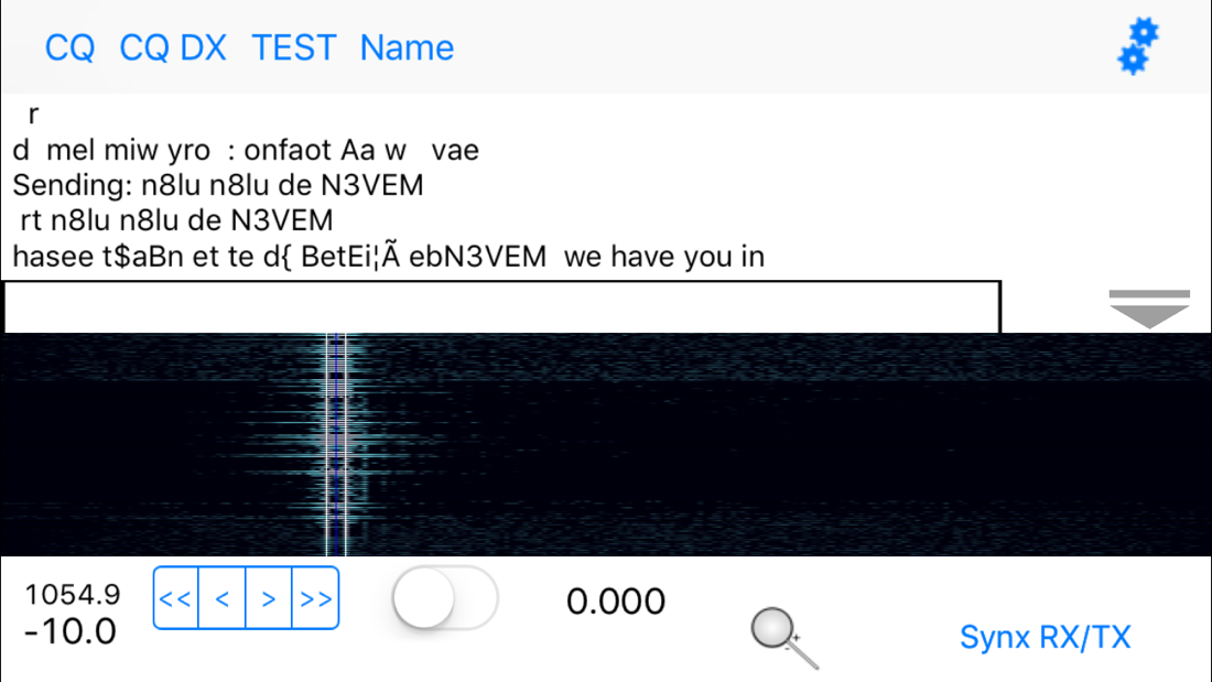
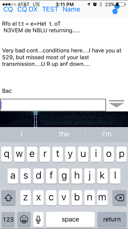
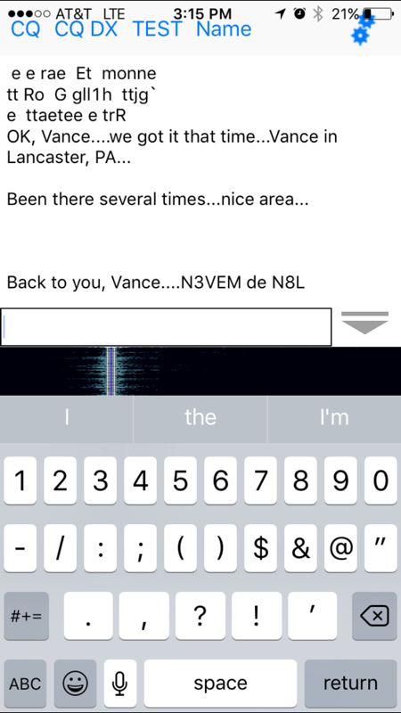
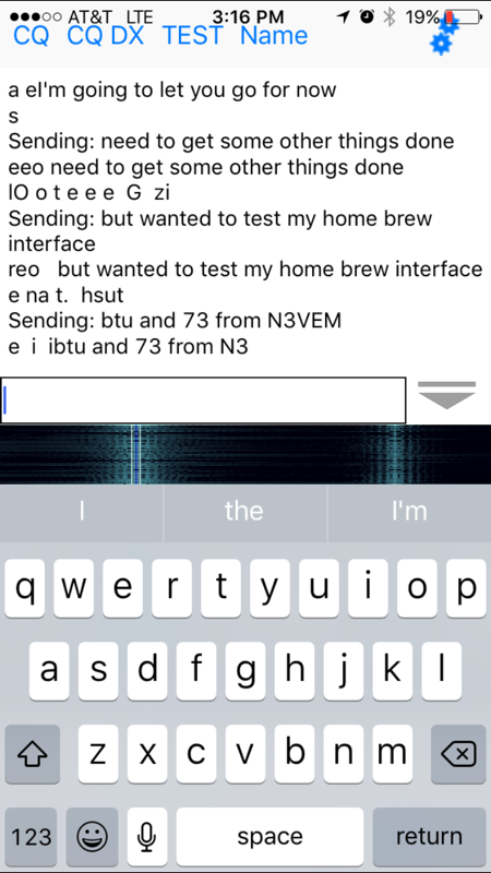
 So, why am I talking about crowd-sourcing? Here's why:
Picture

Did I lose you yet?
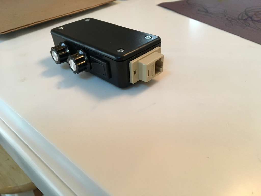
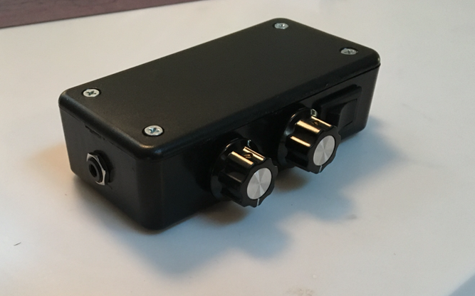
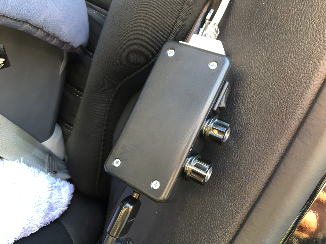
​      I hope not, because I'm finally ready to get to the point. One of the pieces of equipment that my work revolves around comes in these boxes. Recently, we had one that went bad, and it was getting scrapped. After pulling out the proprietary bits, I was left with this box that was just too cool to get rid of. My mind was instantly racing with radio-related ideas to use this for. For some reason, as I was brainstorming, it dawned on me that this could make a fun "community" activity - with the community in question being anyone who happens to stumble on my corner of the Internet, who also has even the slightest interest in, or curiosity about, ham radio.
So, what exactly is the activity? If you haven't figured it out yet, I want us to collectively brainstorm / design / build a project around this box. The brainstorming and designing will be the community effort. The building part will be me, probably exclusively, but a couple of you live close, so I might request to bring in some help if the ideas get too wild :-)
So, with introductions out of the way, I'm going to start with ground rules, then the project constraints, and what we have to work with. Since I am the ultimate builder, and probably the sole financial resource for this project, I will proudly hold the right to change/clarify the ground rules and/or scope at any time I feel it is necessary, and will also hold final go or no-go decisions on anything that involves my personal financial input. With that being said, I will strive to stick to the crowd-sourced intent, and will try to give details and reasons if I veer from that at any point.

Ground Rules

  • No idea is a stupid idea
  • disagreements and discussion are encouraged, but if you get trollish about it, you'll be removed from participation - this is meant to be fun!
  • If you think something "must" be part of the project, convince the rest of the crowd to agree with you (and also convince them to fund it if it is something pricey!)

Scope

Picture
This will be pretty loose as far as project scopes go, but here's the current scope/constraints. This should be interesting, because we're starting with a box, and working backwards, instead of the other way around:
  • The end product must be ham radio centric
  • ​The end product should fit 100% within this box for storage and transportation. Things that need to be taken out of the box and "deployed" for use are okay.
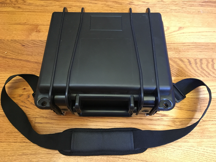
  • This box is a Seahorse Model SE-300. (P.S.  as far as this type of case goes, the Seahorse cases are very reasonably priced!) Inside dimensions of the bottom are approximately 9.5"x7.4"x3". Inside dimensions of the lid are approximately 9.5"x7.4"x1"
  • The parts remaining in the box from it's previous life can either be re-used, modified, completely removed, or replaced, unless otherwise noted
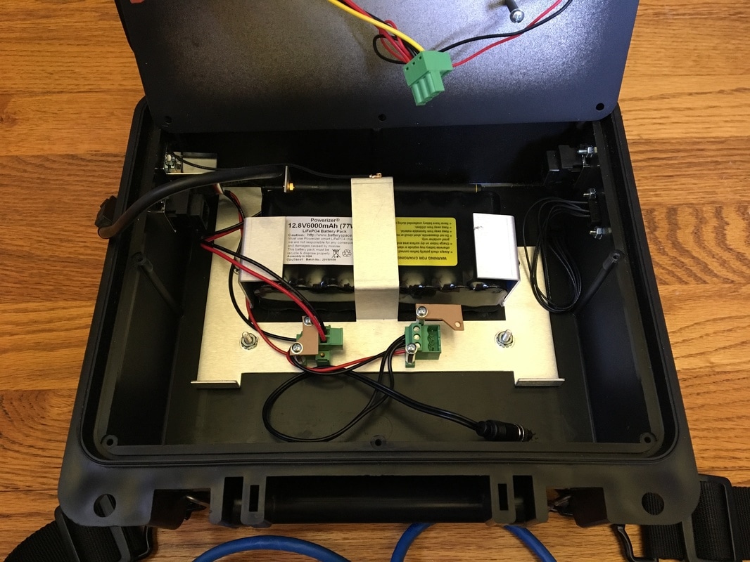
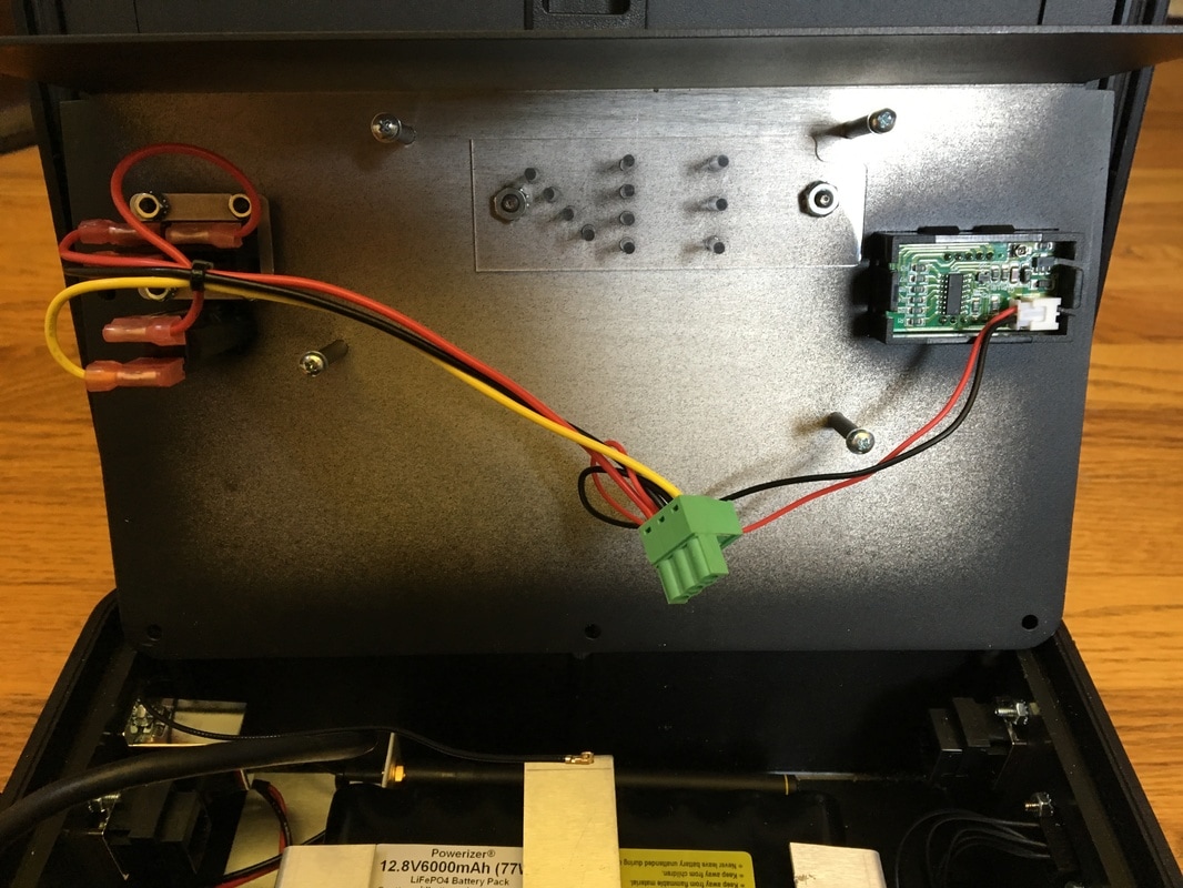
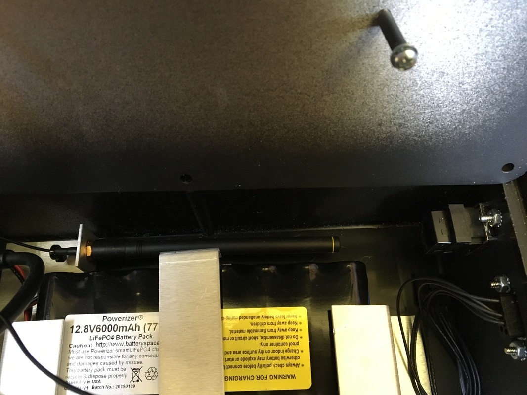
  • The box contains a 12v 6000mAh LiFePO4 battery (and charger). Preferably, this should be the power source, if the end product requires power.
  • The mounting bracket that holds the battery is also the ground plane for a 900MHz antenna that was used in this box's prior life (I have no particular attachment to it, but wanted to let you know that it's there)
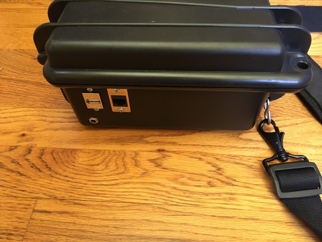
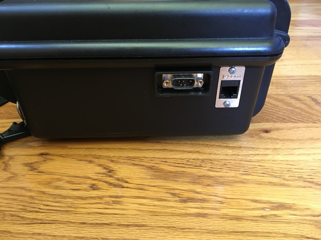
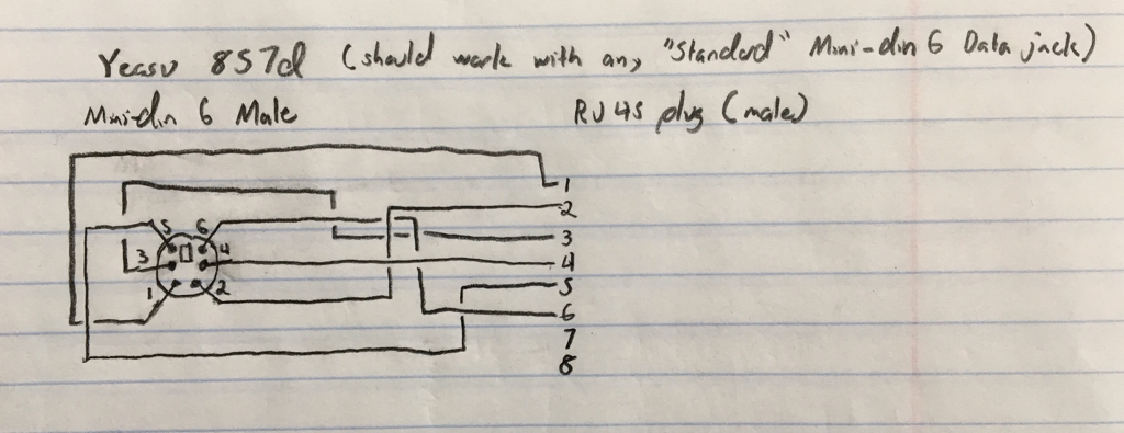
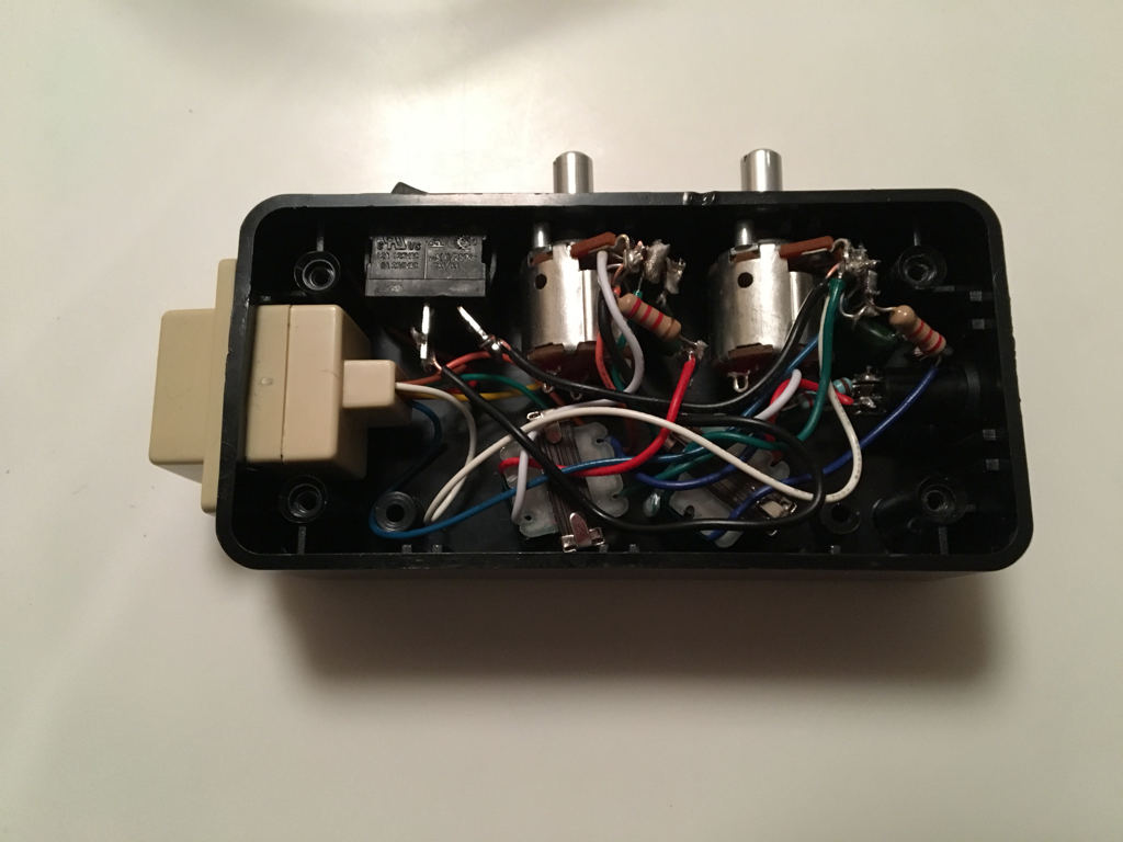
  • The box has the following bulkhead connectors that, in the past, interfaced equipment in the box to the outside world: (2) RJ45 Jacks, (1) DB9 male, (1) USB, (1) coaxial power connector currently used to connect the battery charger
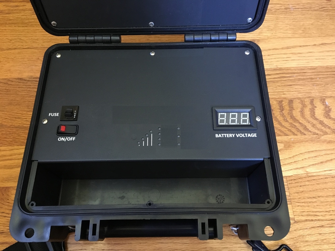
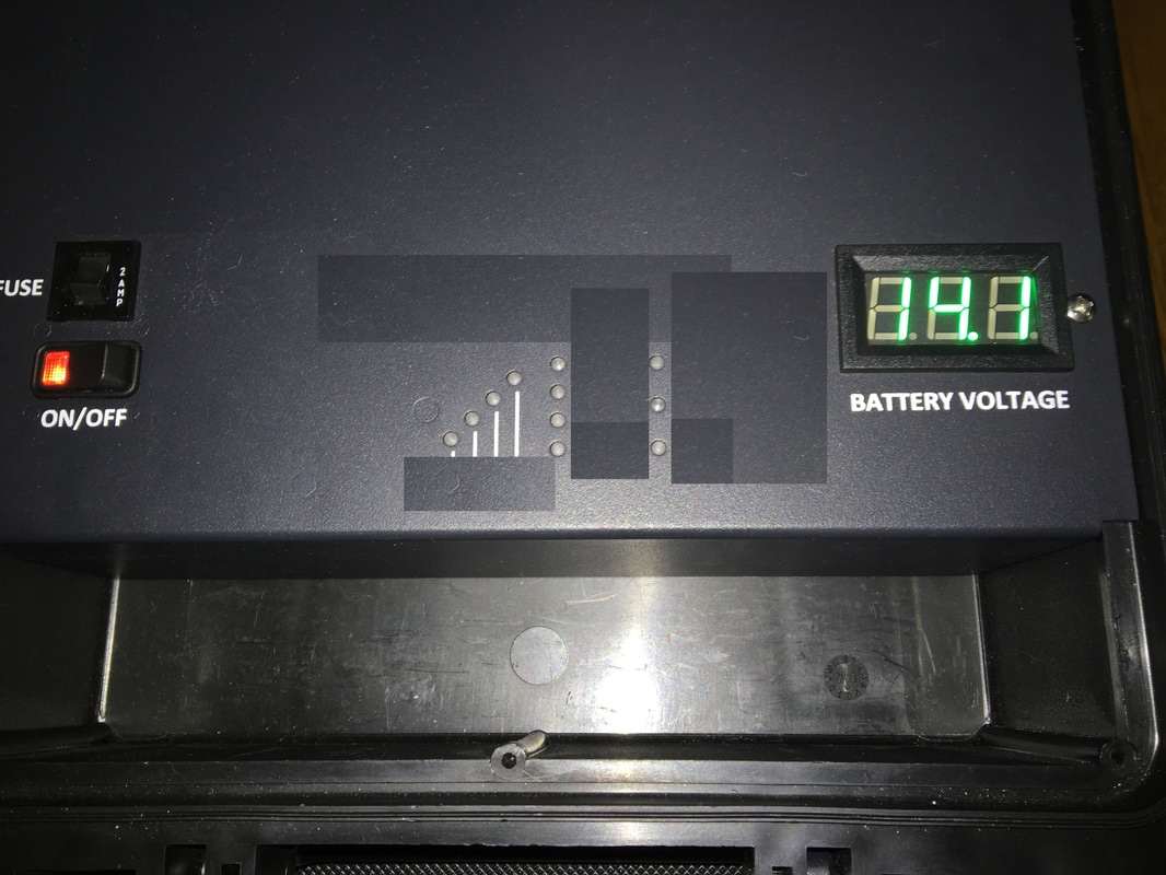
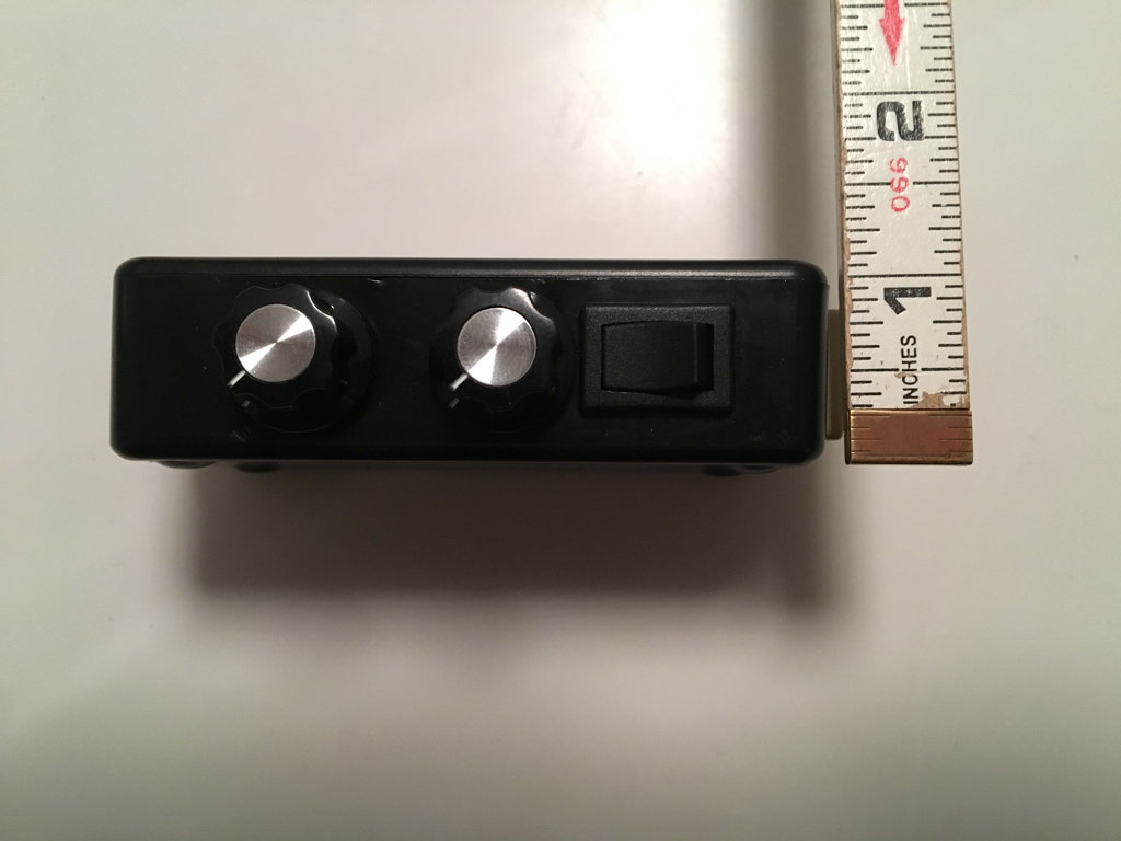
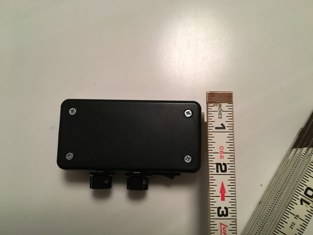
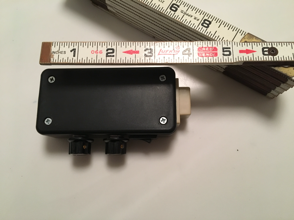
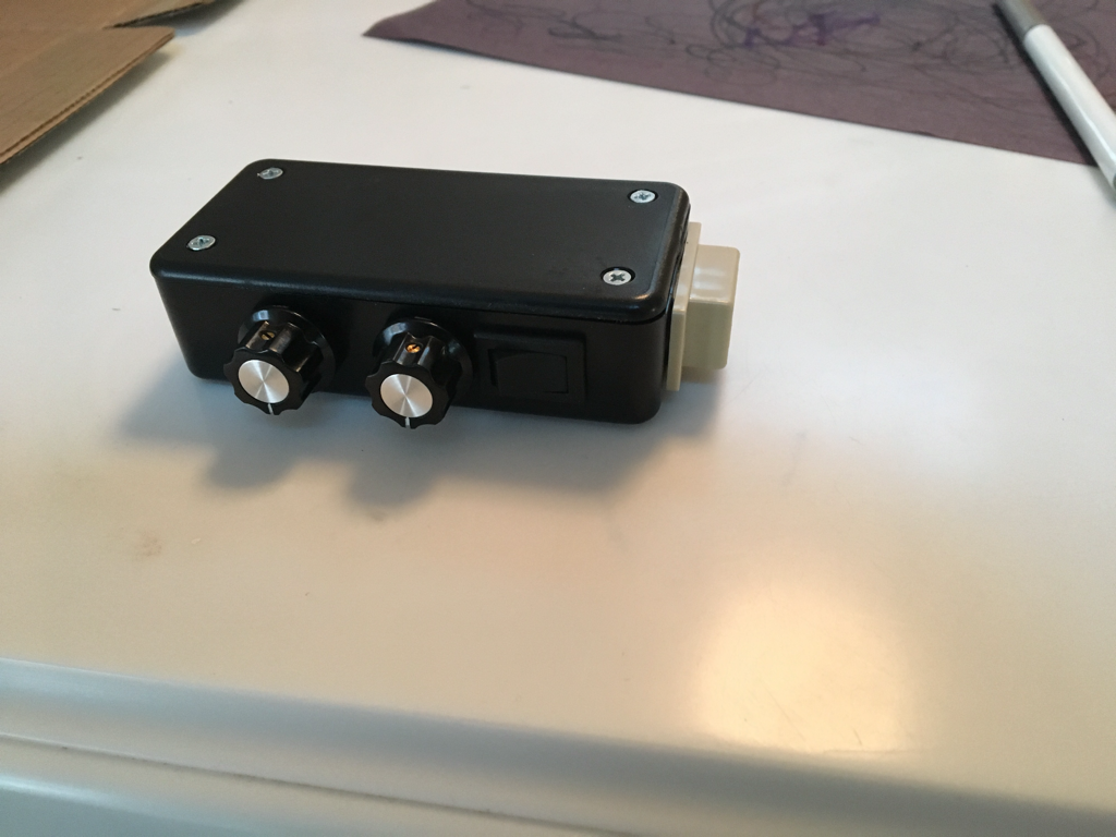
  • Box "display" panel has a 2amp fuse/holder, voltage meter, power switch (switched power from the internal battery), and some holes that previously had LED's shining through them.
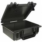
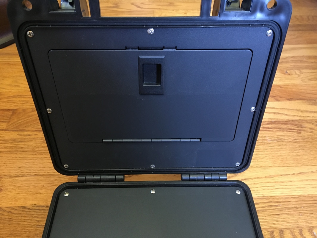
  • The lid of the box has a panel and door, making a storage compartment in the lid.
  • Drilling holes / screwing things into the box / panels is okay
  • Frugality is important. This doesn't mean things have to be cheap, but any cost has to have an associated benefit (I may ask to be "sold" on ideas if they seem pricey)
  • I prefer to reuse / recycle things wherever possible, but will buy parts if suitable things can't be found to re-purpose
  • I have, or have access to, most tools that could conceivably be needed. I am willing to beg/borrow/ask for help for anything I would need to use that I don't have, or don't have experience with (I don't own an Oscilloscope, or Spectrum Analyzer - yet)

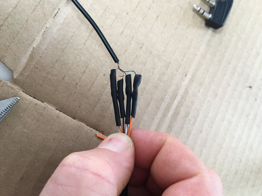
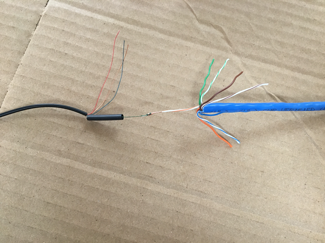
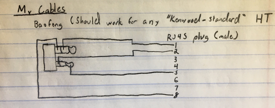
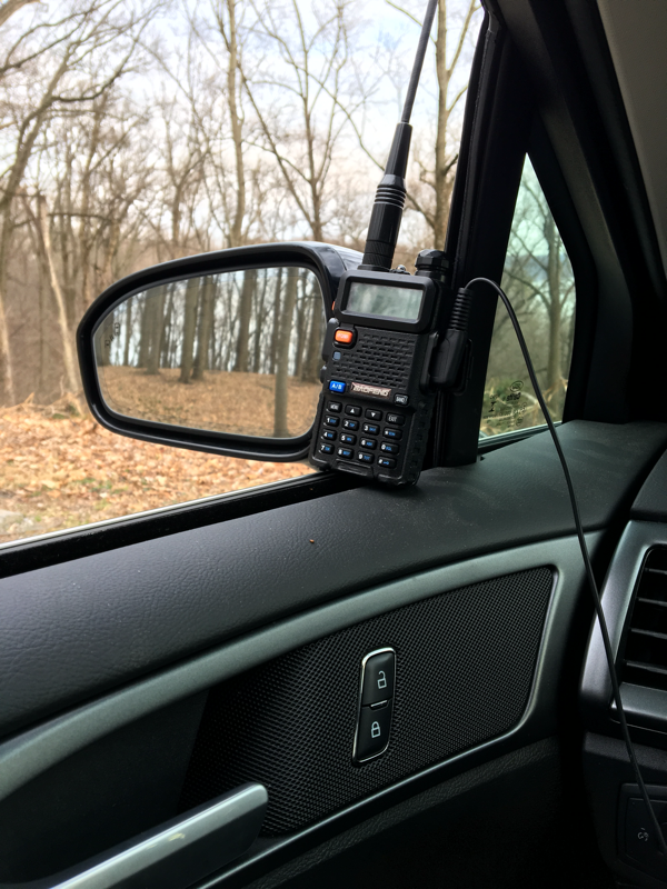
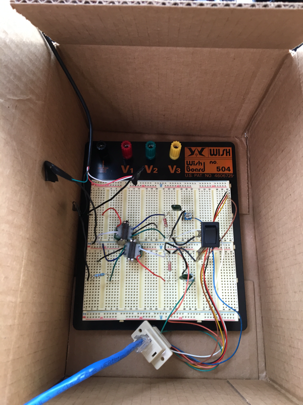
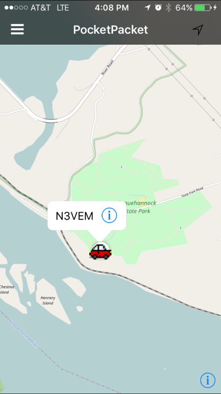
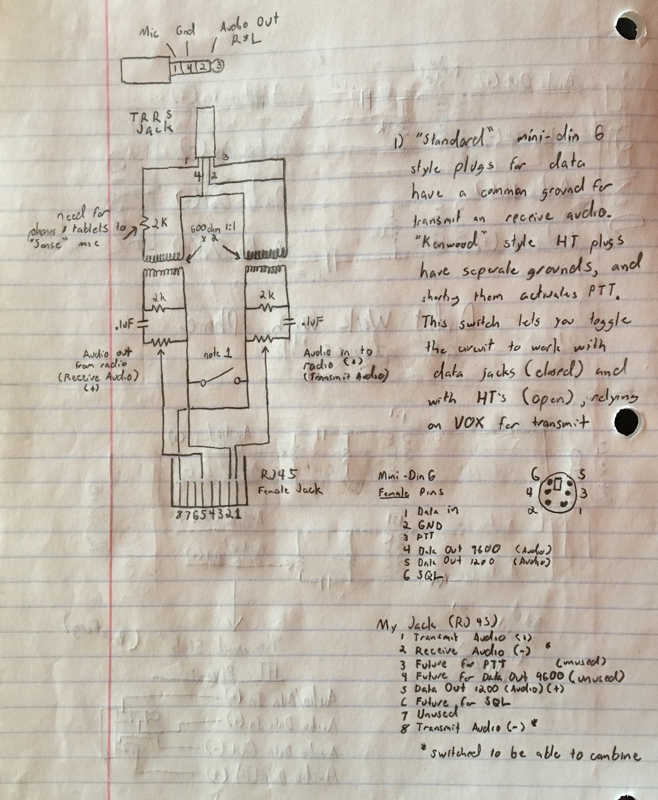
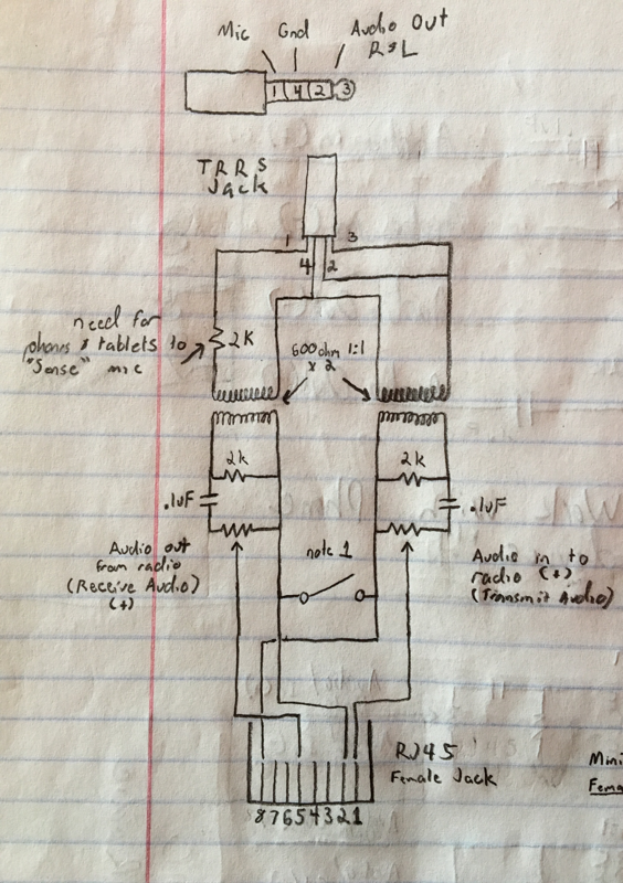
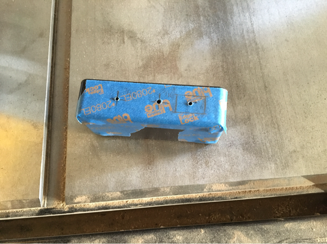
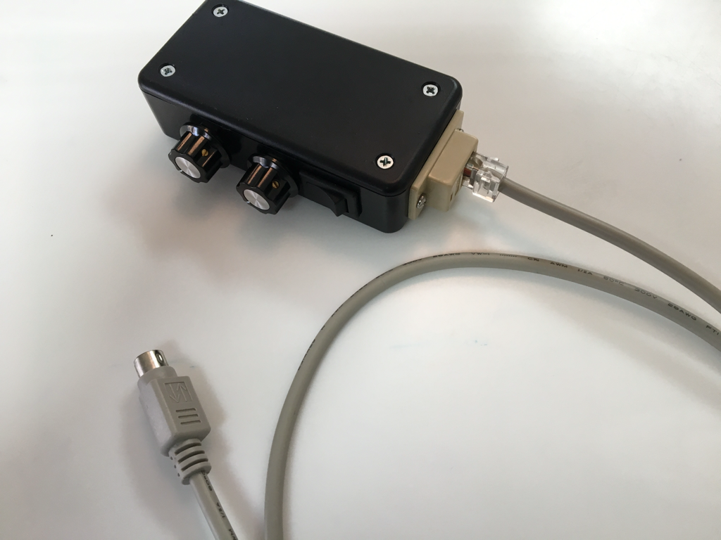
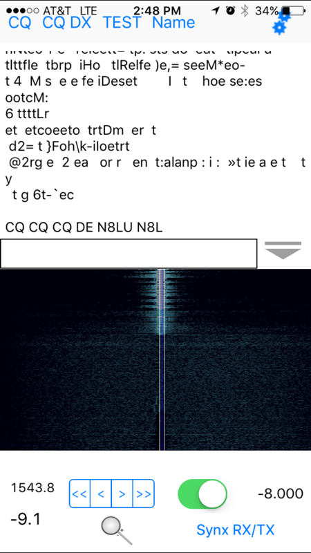
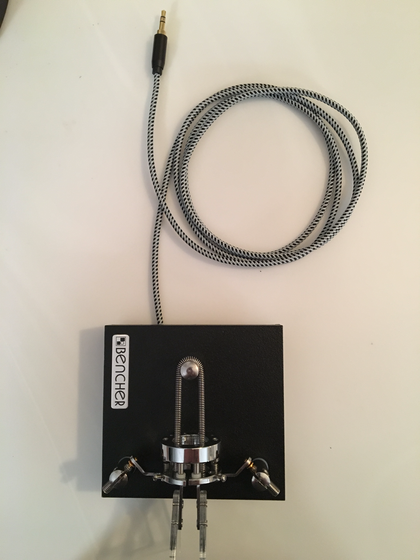
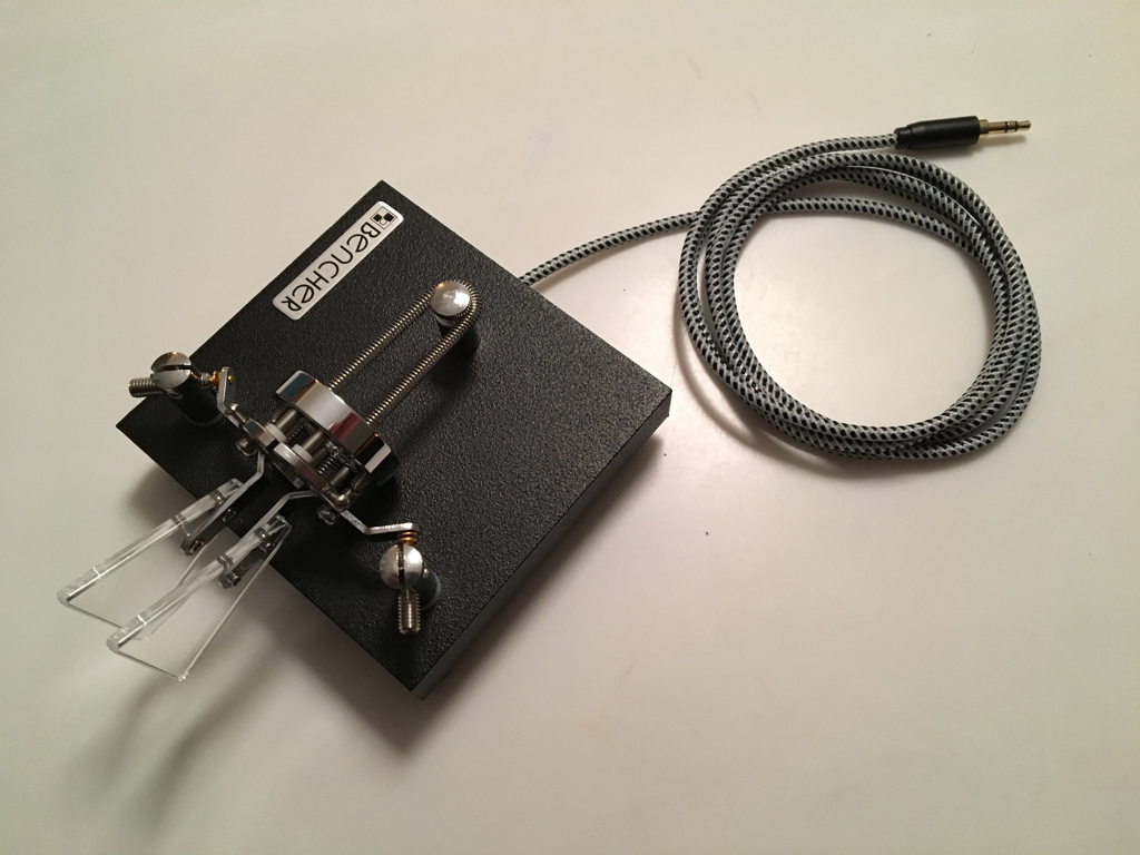
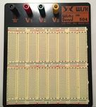
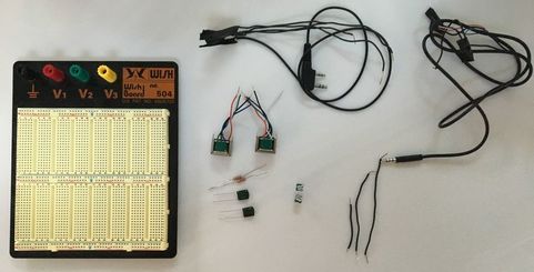
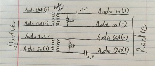
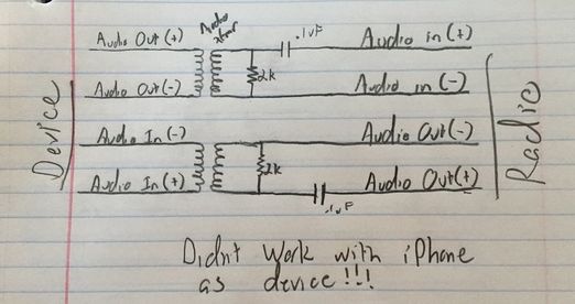
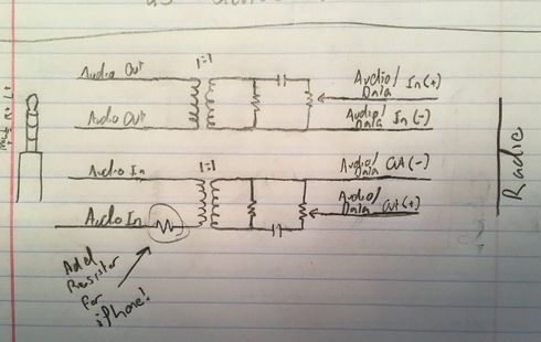
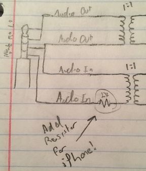
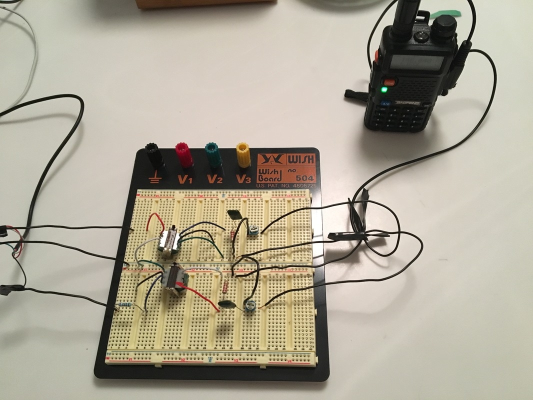
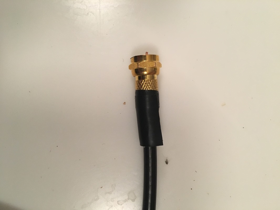
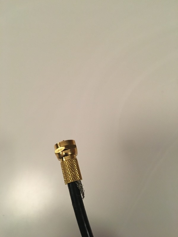
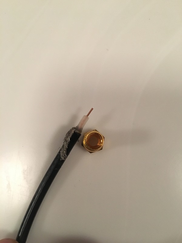
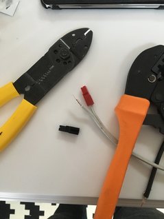
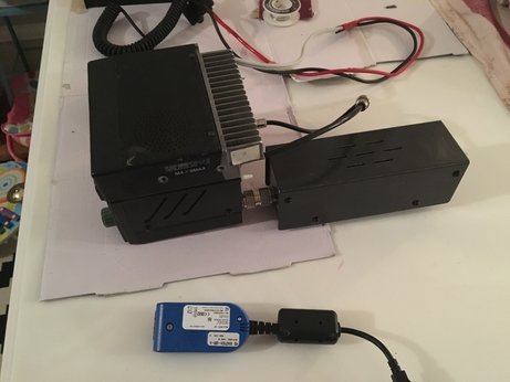
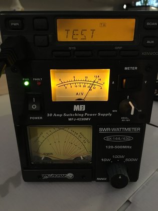
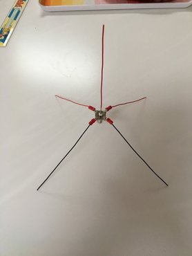
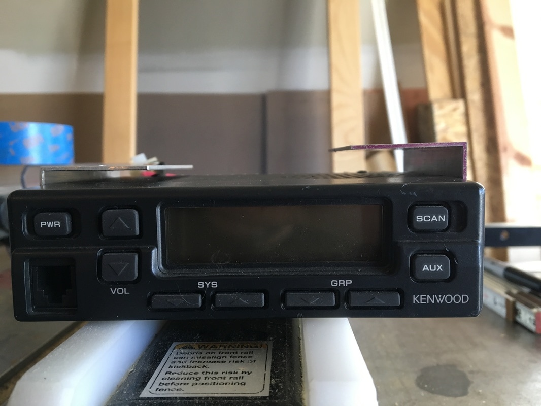
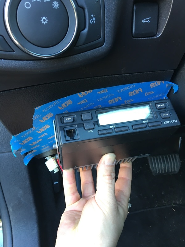
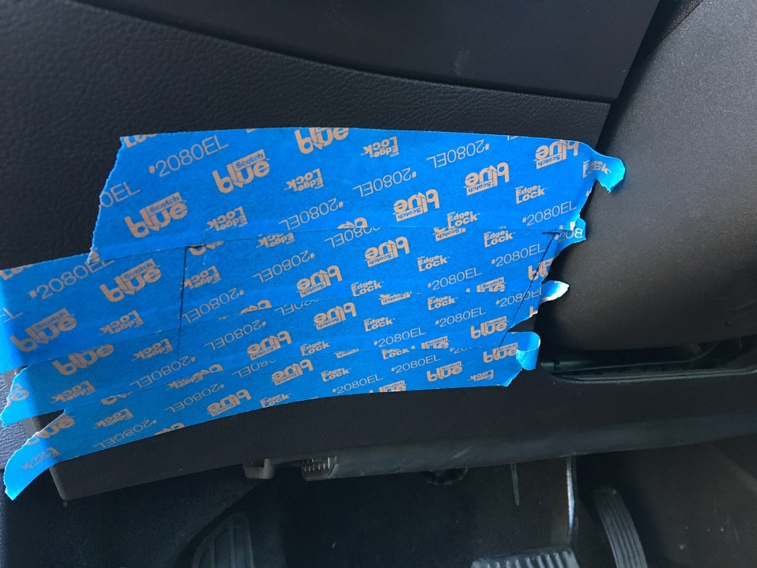
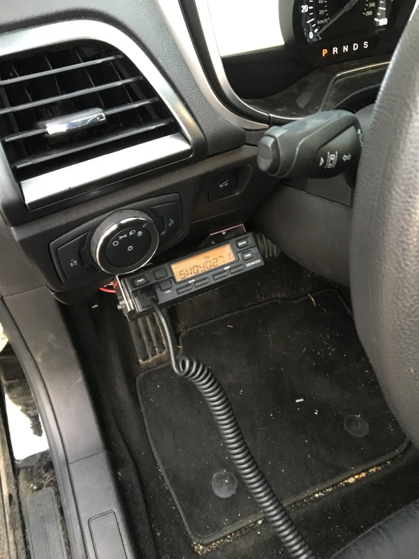
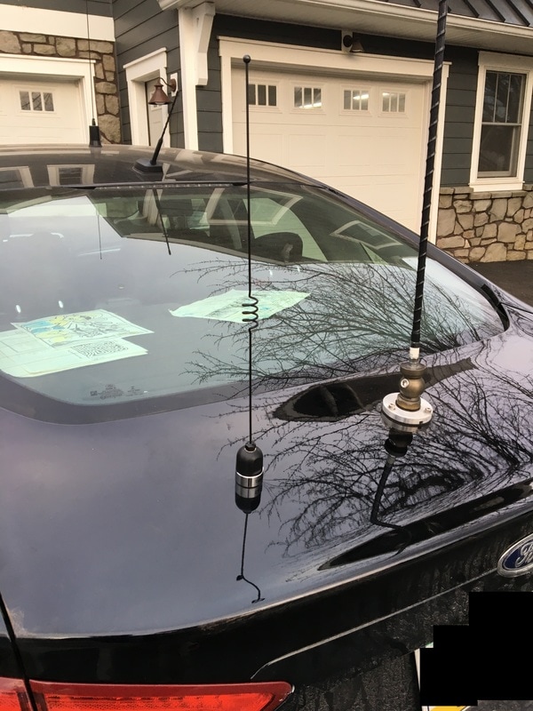
Here are some pictures to help stimulate all those creative juices out there!  (As a note - excuse my bad photo-editing.  I had to hide some proprietary markings.  As the project moves forward I'll paint over those if the panels get re-used.)

​Now, as a member of the "crowd" here is the first assignment. Using the form below, submit your ideas for:
  1. ​The name of the project (as we learned from Amazon and Monster a name doesn't have to reflect what the thing actually is, so we might as well come up with that first - it will be easier to share what we're working on if we have something to call it!
  2. A short description giving a high-level idea for a project. The key here is short - we'll get into details once a project is picked - for now, just stick to ideas like "VHF/UHF go kit", "Flux Capacitor Module", "QRP station", or "Dilithium Crystal Power Box".
After ideas have have been gathered, we'll take a vote! Feel free to discuss and/or ask questions in the comments or on social media, but the final list of things to vote on will be compiled from the submitted forms.
Lastly, be sure to share this with everyone you know! A crowd-sourced project is more fun and more exciting the larger the crowd gets!  We'll keep the suggestion pool open for about a week before I make the list and put it out for a vote!

Suggestions Now Closed!

     Thanks for the suggestions everyone!  The time for submitting ideas has closed, but you can you use the links below to see where the group is in the project, and add your input!
Continue to Part 2
3 Comments

AnnaLink - Finished!

3/11/2017

0 Comments

 
Post contains affiliate links
     For several weeks now I've been slowly working away at a mini-project, building a sound interface to use with my iPhone and tablet for digital modes. If you're just joining me, you can go back and start with part 1, when the project looked like this:
Picture

     To find out what happened between then and now, read on, and I'll share with you how it got from what you see above, to this:
Picture
Picture

     Now, before I get too far, I have to share the fact that if you don't have the patience to "roll your own" you can buy something very similar to this, either complete or in kit form on eBay. There are a couple different versions though, so make sure you get the one that fits your application!  There are models available for iPhone connection, PC connection, different radios, PTT triggered, VOX triggered, etc.  Each one of these is the same basic circuit, but with slight tweaks for each application.
Picture
Easy Digi for iPhone - available on eBay
Picture
Easy Digi for iPhone and Baofeng
Picture
Easy Digi PC soundcard Interface Kit

     When I last left you, I had the interface working, and had already verified that the audio was working in both directions, using one of the world famous Baofeng UV5R radios. With the basic circuit working, I was ready to start thinking about a proper enclosure, and proper cables for connecting my phone and radios.
     The connection for the phone was easy - since modern smart phones and tablets use 3.5mm TRRS (4 conductor audio) cables, I ordered a TRRS jack that I planned on putting in one end of whatever enclosure I ended up getting.  This would let me connect my phone to the device with any 3.5mm TRRS male to male cable.
Clickable Amazon Links!
     The "other" end was something that I debated over. Because I wanted to use this with a couple different types of radios I knew I wanted some type of modular plug so that I could make up at least 2 different cables - one for my HT and one for my Yeasu 857d.
     My first thought was to use an RJ12 jack. These jacks are the same size as the traditional RJ11 jacks used for old-school telephones (does anyone still use house phones?). The main difference is that RJ12 jacks and plugs use all 6 connection points, instead of just the middle 4. When it came time to acquire the part however, this isn't what I ended up getting.  I was clicking around a bunch of different sites, trying to decide where to place my order, and in my late-night clicking stupor I ended up ordering an RJ45 jack instead - as it turns out I'm glad I did!
     The order with my RJ45 jack came first, so I wired it up to the "radio" side of the circuit on my breadboard. To make things tidy, and easy for me to follow I looked up the standard pin numbering for RJ45 plugs. Since I would also be making a cable to connect to the data port on my rig (which uses the standard mini-din 6 format) I also looked up the standard pin numbers for the mini-din format. This way I was able to make the connections on my circuit so that when I was ready to make cables, pin 1 for the radio would equate to pin 1 on my interface, pin 2 to pin 2, up through pin 6.
     As some of you may have noticed, I draw pictures in a notebook when I work on things - doing this helps to cement the concepts of whatever I'm working on into my head. With that thought, here are my notes from working out the pins, and a picture of the jack wired to the breadboard when I was playing around with it:
Picture
Picture

     At this point I was still waiting for a couple of parts from another vendor.  In the interest of working with what I had on hand, I next made up a cable for my Baofeng HT. The actual wires in the HT plug I was using were too small to fit directly in the RJ45 plug (remember those TINY enamel coated wires I talked about?!) Since they were too small I spliced them together with solder and heat-shrink onto a short section of Cat5e cable. I then put a large piece of heat shrink over the entire group of individually spliced wires, and then put the RJ45 plug onto the other end of that, being careful to make sure my wires lined up with the pin-out I referenced above.
     With the new cable made up, and me still waiting on some of the other little parts to arrive, I decided to do another "test" to make sure I didn't accidentally undo any of my previous work, and to make sure that my new modular jack was wired correctly. For this test I put the temporary circuit into a temporary enclosure (aka, a cardboard box) and took it along on a family drive to our closest state park (Susquehanock - I'll probably be doing a WWFF activation here soon.) I successfully sent out a couple packets via APRS so I know the cables and jack were wired up correctly!
     Now, at this point the most observant among you might be saying, "Hey, I see a switch in the circuit on your breadboard in some of those pictures...you never mentioned a switch!" To you I say, "good catch!"
     Something I realized while I was working on this is that on the "radio" side of the circuit the mini-din connectors only have 1 ground connection that is shared for all of the other connections, while the Baofeng or Kenwood style HT plugs need separate grounds for transmit and receive audio. This is because on these radios, connecting the two grounds together is what activates the PTT. The switch gives me a way to use the same devices for both radio types. With the switch wired between the 2 grounds, leaving the switch in the open position lets it work with HT radios (using VOX), and putting the switch in the closed position makes it work with standard mini-din data ports (also using VOX.) With all these little discoveries, I'm finally ready to share my "final" schematic for this circuit....
Behold! The AnnaLink schematic as it appears in my notebook:
     Shortly after this, my mini-din 6-pin cable arrived. I ordered one that was 6 feet, and male to male, so that I could cut it in half and make up 2 cables. Wiring it up when it came was pretty simple because of my care to make sure the pin numbers would match up in a 1 to 1 relationship:
Picture

     Next, it was time to finally put this in an enclosure. I made a trip to the local Radio Shack (stuff is on clearance since they're apparently closing another round of stores and filing bankruptcy-again...) and picked up the smallest project box I thought I could fit everything in. At this point I also picked up 2 different potentiometers because I wanted something I could mount in the box, and put knobs on. I ended up getting audio taper potentiometers instead of linear, because the rate at which they change the level (logarithmic) is supposed to feel more natural for audio applications.
     Once I had these in hand, I also decided at that point that I would just mount everything in the box and do point to point wiring, because the number of components is small, and I could rely on the potentiometers to be the physical strength, and simply attach the smaller components directly to them. The pictures below show my markup method for making the holes, and the final product:
Picture
Picture
Picture
Picture
Picture
Picture
Picture
Picture
Picture

     For those of you who were patient enough to hang in there through all of this, here's some proof that it all worked! A contact with N8LU using 5 watts from my 857d, and the PSKer app on my iPhone. This app has mixed reviews, and I'll share my own full review at some point, but as far as I can tell it's the only iPhone app that will both send and receive PSK31 using the phone as an audio modem, so despite its shortfalls, it's the best (only?) one out there for iPhones (there are more options if you're an Android person.)
     With that, this looong post is finally over! Thanks for sticking around, and feel free to ask me questions or leave comments - especially if you plan on building your own!
Back to Part 2
0 Comments

Details

3/8/2017

3 Comments

 
Post contains affiliate links
I had the day off work today, but with the hectic life in a house where the kids are 5 and 1, I didn't get to do much Radio. We did run some errands, so I got to spin the dial a little bit from the mobile, but there's not much to talk about on that front today.
For me, the exciting radio activities for the day were in between other tasks, and after everyone went to bed. Earlier today, while my YL was picking up our daughter from school, I had the chance to add a couple more pieces to the sound card interface I've been playing with. I'll write more about that in another post because I made a couple fun little tweaks to it. Later on, after everyone went to bed, I finally put a cord on my new paddles:
Picture
Picture
This might not seem that exciting to many of you, but I felt like my paddles needed something nicer than just a PVC covered cord. Luckily, I found a nice cloth jacketed cable on Amazon for just a couple dollars - I think it adds a touch of refinement, don't you?
3 Comments

AnnaLink

2/26/2017

3 Comments

 
Post Contains Affiliate Links
      Welcome to my promised follow up about the sound card interface that I've been playing around with!  If you didn't read about my initial attempts at making a basic interface to connect my iPhone and  Tablet to my rig, check out Part 1 here!
Picture
     In case you're curious, this post is called AnnaLink because that is now the official name of this little project.  My daughter "helped" me put this together - which really consisted of me explaining a schematic, and her just nodding, and asking when she could poke parts into the breadboard....apparently that was the fun part :-)  Anyway, as she was having fun poking resistors and things into the little holes, she asked me "Daddy, what are we going to call it?"  I told her it should have "link" in the name because of what it does, and AnnaLink is what she decided, so AnnaLink it is....  If you read part 1 of this little project, you know that I actaully already had this mostly put together.  If you happen to follow me on Instagram or Twitter: 

you also got a sneak peek at my test drive where I put the whole thing on the dashboard of my car, and drove down the road to fire off a few APRS packets using my iPhone and HT.  (Psst....I sometimes throw random pictures of stuff up on Twitter and Instagram before I write my posts, but don't tell - it's a secret...)
     So what was I working on?  Well, between my last post on this project and my test drive, I learned a couple things about the circuit I put together.  I had also promised a couple sketches of the circuit in case anyone wanted to play along.  With that in mind, I started this evening by sketching out the circuit, tearing the circuit apart, and then putting it all back together following the sketch.  I did all that so that I could double check my own work.  Here's how it went:
     The first thing I did, was to pull everything back off the bread-board and lay it out.  When you look at it this way, it's obvious that this is a very basic circuit, because there aren't really that many parts:
Picture
     And since we're starting from the beginning, I'll start by showing you the schematic that I first found online.  There are piles of this exact same diagram that pop up when you do a Google search for "Soundcard Interface", but they all follow this basic layout (P.S. I am not an Electronics Professional - just a hobbyist, so if my diagram doesn't show something "correct" and you are offended, feel free to comment and let me know, that's how we all learn!  If you're nasty about it though, I'll just ignore you...)
Picture
     If you'll recall from my prior post, I mentioned that I tested, and verified, that the audio from my iPhone traversed this circuit just fine.  The catch however, that I found prior to my test-drive, was that it didn't seem to be working the other way around - audio wouldn't get back into my iPhone through the mic connector.  After a lot of grumbling, poking at stuff with my multi-meter, and lots of Googling, I found out what I was missing, in the corner of some internet forum (can't remember which one - sorry!)  What I found was something that was new to me, and might be new to anyone that hasn't had much experience with modern smart-phones and tablets:
     Older devices and larger devices use a mic jack that has extra contacts in it, that act as a mechanical switch to sense when something is plugged in.  Newer devices, and devices that have a small footprint no longer do this mechanically - they do it electrically.  The mic connector actually provides a bias voltage that needs to pass through a resistor in the device being plugged in, before it will recognize that something is plugged into the mic port.  On the iPhone, if you have a direct short between the mic (sleeve on the TRRS connector) and ground (one of the Rings on the TRRS connector) it ignores the mic, because this is exactly what happens when you plug in normal headphones (that don't have a mic.)  By design, this is good for most users, because it lets them listen to the iPhone on traditional headphones, but use the microphone on the phone to talk, if needed.  
     For the circuit I made, this meant that my iPhone was ignoring the mic, and trying to use the built in speaker-mic because there is a direct DC path between Mic and Ground!
Picture
     Luckily, once I was finally enlightened to how the mic sensing worked, the fix was pretty simple - stick a 2k resistor in the path for the microphone!  As a note, in my drawing below, at this point I also sketched in the two potentiometers that I added so that levels passing through the device could be adjusted.  Putting them in the circuit this way just makes a voltage divider.  If you're very new to electronics the website All About Circuits has a lot of useful information, projects, and even a free textbook series, if you're not sure what I mean by voltage divider.
Picture
     Of course after I went through all this, I happened to stumble on an interface for sale on ebay, advertised to work with the iPhone.  Looking at the circuit on that device (a schematic was included with the pictures!) I could see that the needed resistor was included in their design.  Why couldn't that have been the schematic I found first?!  Oh well - this way I know why the resistor is there, and can share that info, rather than just saying that it's there because the picture told me to put it there :-)
     To connect this to my phone I grabbed a headset extension cable, and just cut off the end I needed, along with a a foot or so of cable.  If you happen to have an old headset lying around that doesn't work, repurpose that cord!  The connections to the plug can be sounded-out with your meter, but on mine the wires went like this:
  • Left Audio Out - White
  • Right Audio Out - Red
  • Ground - Green
  • Mic - Black
Here's a picture though of which pin should be which, in case you have different colors:
Picture
     So, enough of my bad scribbles, here's a picture of the real deal, on a breadboard, after my daughter did the fun part of poking the parts into the right holes:
Picture
     I had an earpiece from a Baofeng radio that was junked but the plug and cable were still good, so I scavenged that to make up a connector.  Here's another tip - this is something I never knew because I never worked with wire this small before..when you strip the outer jacket, the individual conductors in these ear pieces are TINY.  They way they are made is that each individual "hair" in each bundle is coated in enamel, so you can't really strip the wires.  Essentially, you treat them like you would a bare wire - tin the ends, and then solder them - the heat in that process melts away the enamel and then the wires can make contact.  This might be old news to folks who have worked with small wire and magnet wire, but it was new to me!
     Doing the above allowed me to verify that this would work for anything with the Kenwood "style" of plugs.  I verified the receive audio portion by tuning to a local repeater and recording the conversation that I heard using the "Voice Memo" app on my phone. I then verified that the transmit audio portion was working by taking the drive I mentioned at the beginning of this post - I used APRS.fi to make sure my packets got out - worked great!
     If you want to mimic the same thing, the connections on this style of plug are pretty straight-forward as well, and are also spelled out in many places online....here's my low-tech version of that diagram:
Picture
     Here's a couple of shots of the plug wired up, and the receive portion in action.  I couldn't get a shot of the transmit because APRS packets burst out so fast that the transmission ended by the time I could get my phone to take the picture - after a couple attempts to catch that in a photo I gave up :-)
     Whats next for this little mini-project?
  • Order a connector so I can wire something up to connect to my Yeasu 857d
    • I grabbed an old keyboard at a thrift shop for this because it had the right connector (PS/2 = Mini Din-6), and was cheaper then buying and shipping the actual connector, but it turned out the connector on the keyboard wasn't actaully using all the pins, and a couple of the missings pins were ones specifically needed to connect to the data jack on the 857d.
  • Test it out using my 857d and make some PSK and SSTV contacts
  • Build the circuit in a more permanent way
  • Call it done!
     Are you interested in playing along?  Below is the stuff you will need, with clickable Amazon links.  If you look around you can probably find these same items cheaper by getting exactly the quantity you need, but with these types of things it never hurts to have spares for your project stash. Many of these things are small, so for a small amount of money you can have everything you need to replicate what I did, AND have a bunch of stuff left over for your project box!
Breadboard and Jumpers together in one package!  This type of arrangement is the basis for a lot of my experimentation with small circuits.
Audio Transformers.  In ham radio these are great to have around because they can be used in quite a few sound applications where you need to isolate devices from each other!
2k Resistors.  You might already have a stash of these, but if not, start your stash now!
.1 uF Capacitors.  These are another item that might already be in your junk box, but if they aren't, you can get them here so that you can piece together your very own interface!
Potentiometers.  Some people refer to these as variable resistors.  They are pretty much the standard way to make an adjustable voltage divider so that you can control output / input levels of circuits like this one.
Baofeng Headset.  If you want to connect this to an HT that uses the Kenwood style plug, this is a pretty cheap way to buy the plug, with wire attached.  Just cut off the earpiece and use what's left!
TRRS Extension Cable.  For how cheaply you can get these cables pre-made, if you don't have anything to make up a cable, it's just as easy to get one of these and cut off the end you don't need.
     I'll be sure to post another update when I get my cable made up and test this with my Yeasu 857d.  If you happen to frequent the PSK or SSTV frequencies, you might even catch me on the air when I'm testing it out!

​Bye for now!
Next - Part 3
Back to Part 1
3 Comments

Can I buy You a License?

2/24/2017

0 Comments

 
Post contains affiliate links
     Believe it or not - it can be that simple.....What radio license can you just run out buy?  GMRS.  
     GMRS (FCC Part 95 Subpart A) is a radio service intended primarily for family communications (although there are some older businesses grandfathered in.)  In case you don't know about GMRS, it is basically a service where you are required to be licensed, but the only stipulations for getting the license are having about $60 available to mail to the FCC, being a person (not a business, government, or representative of one), and being 18.  Once you've done that, you, and anyone you're related too, can use your license.  
     GMRS is very similar to the little blister-pack radios you can buy at the chain stores.  Those radio's are normally part of the Family Radio Service, or FRS.  There are some shared frequencies between FRS and GMRS but power levels and allowable antenna types vary.  The biggest difference is, that you can use more power, larger antenna's, setup and use repeaters, etc. with GMRS.  There are a limited number of frequencies (specific channels) that you can use, but that shouldn't be a hurdle.  There are even commercial UHF mobile and HT radios out there that are type accepted for the GMRS service, so if you can get your hands on them, you can actaully put together a decent little station.
     So why am I writing about GMRS?  Because of my daughter!  She has been expressing a lot of interest in my ham radio activities, so I decided that setting up a couple GMRS radio's would be a good way for her to be able to "practice" for the big show!  The idea was to put 1 radio in the house, and 1 in my car, so that when I'm around town, we can chat, without the need for me to be standing over her shoulder.  With that thought in mind, this saga began around christmas time - and what a saga it turned out to be...

Who can use the GMRS license?  Pretty much anyone who would show up at your family reunion.....
(1) Licensee;
(2) Licensee's spouse;
(3) Licensee's children, grandchildren, stepchildren;
(4) Licensee's parents, grandparents, stepparents;
(5) Licensee's brothers, sisters;
(6) Licensee's aunts, uncles, nieces, nephews; and
(7) Licensee's in-laws.

     We ordered some Kenwood TK-840 commercial radio's online just before christmas.  Based on the searching I did, these radio's were type accepted for GMRS. Getting things off ebay, you never know what to expect - and this proved to be no different.  The radio's came, and the first thing I noticed was that there were F connectors, instead of anything normally used for radio, on the coax pigtails.  To make things even more interesting, they weren't even really attached.  It was almost like someone had gone to RadioShack, bought some connectors, and just kind of jammed them onto the end of the coax.  Whoever did it wasn't even good at applying electrical tape...
     Luckily, the coax itself seemed to be properly connected, so I figured we would just make putting connectors on part of the project as my daughter and I got these radio's ready to go (her first lesson in solder was about iron safety!)  Next came the power leads.  Again, it wasn't technically the proper cord, but I found out what it was that had been used, and looked up the current handling capacity, and it was rated for enough current to handle what these little radio's would do, so we added some powerpole connectors.
Picture
     With the powerpole connectors on (this goes WAAAAY easier with the proper crimper!!!), and proper RF connectors in place, I hooked the radio's up to a dummy load, through a meter, just to make sure they worked.  Everything seemed to be in order - so far so good!
Picture
     The next step was to get my hands on the programming software for these rigs.  That software, which was made by Kenwood, is called KPG25D.  It isn't officially available any longer, but through the magic of the internet most people can get ahold of it fairly simply.  Writing out all the details of how to use the software would take up a lot of space, so I'll just leave it at this - you'll need this stuff, which you can find online if you search around a bit:
  • The programming manual (or you can just sort of figure it out as you go)
  • The KPG25D programming software
  • This is DOS software, so another catch is that you either need to get your hands on an old computer, or use a DOS emulator - I used DosBox 
  • A USB to serial converter cable (if your computer doesn't have a serial port)
  • The Kenwood Programming cable that matches the radio

     All this does take some finagling, but Google helped me, so you can either search around like I did, or contact me and i'll help answer any questions you might have!
     Armed with all the stuff above, we programmed the GMRS frequencies into the radio's, and fired them up for a test:
Picture
     For the astute folks out there, you'll notice that the power meter isn't budging - for some reason these radio's, which worked fine before I reprogrammed them, now won't transmit!  I poured through lots of notes, and eventually realized that I had gotten version "2" of these radio's which only work on the commercial portions of UHF, and are now basically worthless because they are wideband, so they can't be used in commercial service any longer, and they won't transmit anywhere in the amature or GMRS bands.  Grrrrr.....no wonder they were so cheap.  (Anybody want to buy 3 worthless radios?  If not I'll hold on to them - maybe I can use them as exciters when I start building microwave transverters....)
So, with that lesson learned the hard way, we went back to ebay and paid just a bit more. This got us 2 additional radios that were the proper version. While we waited for them to arrive we (my daughter and I) spent a couple hours one evening passing the time by building her very first antenna, tuned specifically for the GMRS frequencies:
Picture
     As soon as the new radio's arrived, we opened them up, and thanked our lucky stars that these were in much better shape (a Ham must have had them!) - all we had to do was add powerpoles to the power leads, and we were ready to start programming radio's.  After we had them programmed, we connected the antenna to my daughter's radio, and a dummy load to mine (P.S, a dummy load will work as an antenna over short distances....sometimes even long distances as many will attest to!)  We then had a short test conversation from one end of the kitchen to the other - awesome!  Working Radio's!
     Next, we had to decide where to install my little helpers radio.  Putting radio's around the house can be an interesting exercise, because the install location needs to meet the criteria of everyone who might be involved - in this case, the criteria was:
  • Somewhere near power so I don't have to run a long cord
  • Somewhere easily accessible to my daughter
  • Somewhere that she will be within earshot of adult when she's using it
  • Somewhere that it isn't seen during day-to-day living
  • Somewhere that we can put her small antenna now, but eventually run a line to a rooftop antenna
     The spot that met all these requirements was the cabinet that I just recently built into the entryway from our garage - it has power in it, because we wanted to be able to charge phones and such, it has shelves and hooks for our little ones' things, it's pretty central in the house (so when little operator is using it she'll be heard), AND it is normally behind closed doors, so no one has to see it that doesn't want too.

     With the little one's radio installed, it was time to make some new holes in my car!  I started by making up some brackets to mount the radio.  Because the surface where I was going to put this wasn't level, I needed one side to stand out further than the other, so custom making a bracket from aluminum angle was the word of the day.  While making those brackets, and marking the mounting locations for everything, I did my normal marking method - I covered the area with blue painters tape, and made all my measurements and marks on it.  After drilling away, I peeled the tape back off.  I use this same tape method when I drill a hole for antenna's as well.  this does 2 things - it makes it easy to mark and measure where to drill without leaving any permanent markings, but it also servers to "catch" all the little metal shavings from the drilling, so they don't lie on the finish of the car and cause rust spots.  
     Finally, after a couple months, this project is complete, and my daughter can talk to me while I'm tooling around town.  If you happen to be on the GMRS bandwagon and you ever hear a little girl and her dad talking about random nonsense in the Lancaster, PA area, and using the callsign WQYQ271, that's us!
0 Comments
<<Previous
Forward>>

    Categories

    All
    Antenna
    Cw
    Digital-modes
    Flying-with-gear
    Home QTH
    Miscellaneous
    Mobile
    Operating Events
    Portable
    POTA
    Shack Build
    Technical


    - N3VEM -

         Welcome to my Ham Radio Blog!  This blog was started primarily to share my two concurrent shack builds - my mobile station and my home station.  Over time, this has grown to include sharing about my operations, and general radio-related thoughts that I have as a newer operator.  
         
    ​Enjoy!

    RSS Feed


    Picture
    POTA!

    Picture
    Proving that hams do indeed still build stuff!

    Picture
    100 Watts and Wire is an awesome community, based around an excellent podcast. 

    Archives

    September 2020
    July 2020
    January 2020
    September 2019
    August 2019
    July 2019
    June 2019
    May 2019
    March 2019
    January 2019
    December 2018
    November 2018
    October 2018
    September 2018
    August 2018
    July 2018
    June 2018
    May 2018
    April 2018
    March 2018
    February 2018
    January 2018
    December 2017
    November 2017
    October 2017
    September 2017
    August 2017
    July 2017
    June 2017
    May 2017
    April 2017
    March 2017
    February 2017
    January 2017
    December 2016
    November 2016
    October 2016
    September 2016
    August 2016
    July 2016
    June 2016
    May 2016
    April 2016
    March 2016
    February 2016
    January 2016
    December 2015
    November 2015


Picture
Copyright © 2015
 Vance Martin is a participant in the Amazon Services LLC Associates Program, an affiliate advertising program designed to provide a means for sites to earn advertising fees by advertising and linking to amazon.com.