While I can't help you out with sourcing a back-box exactly like this, I can share a link for the power supply. I chose the IOTA DLS-75 because they can be had relatively inexpensively, and for a large switcher, they seem to get pretty decent reviews from other hams in regards to being RF quiet etc. The model I got is a combined power supply / batter charger, so it will also cover me for future battery-backup when I'm ready to add it.
|
This is the exact model that I picked up. You can click on the picture to grab one from Amazon, or if you're lucky like me, you might be able to snag one from ebay for a little bit cheaper.
|
Once I had this stuff and started wiring things up, I realized pretty quickly that I had a noisy fan in the power supply I got, so I ordered a replacement fan. At the same time, I ordered a couple other tidbits:
The little green thing on the right is a din-rail mount dc current sensor, good for up to 100 amps!
There's still a lot of bits I need to add, and wiring to tidy up as I do it, but as I started piecing things together, this is what it started to look like:
Wiring up the DC current sensor was pretty easy - feed it power with anything from 8 - 35 volts, and then read the voltage output from the sensor connection terminals. 2.5 volts is 0 amps, and up or down from there gives your your current in either direction (after throwing it into a quick formula to convert the voltage to current). Since this measures current in both directions, you could easily use this to monitory battery charging/discharging as well!
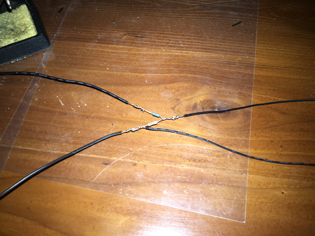
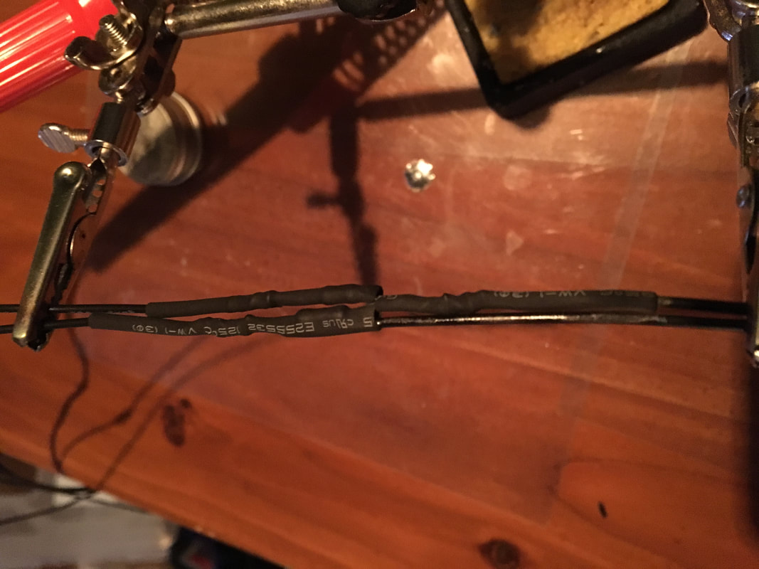
To monitor the main voltage, I just whipped up a little voltage divider to feed the arduino. Rather than use something specified somewhere, I just sat down with this calculator, and the pile of resistors in my junk-box until I found a combo I had that worked well. I then wired up the resistors into a harness, so the voltage divider is now in-line in the wiring between the the arduino and the bus bars where I connected to sample the voltage.
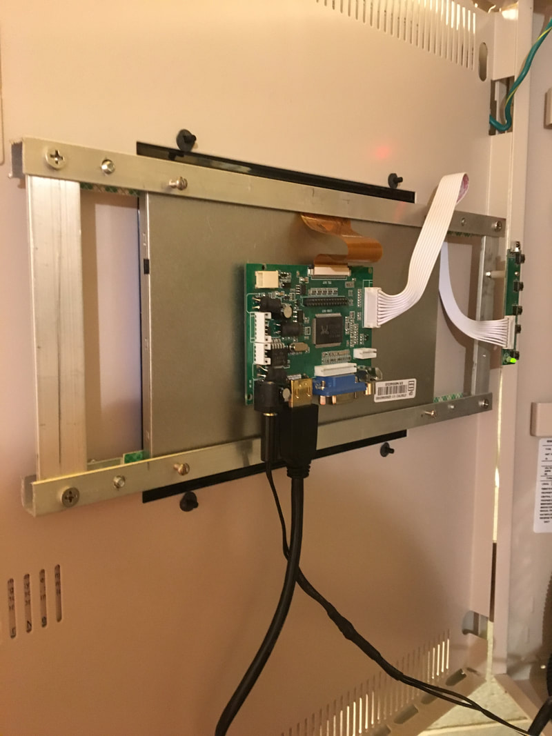
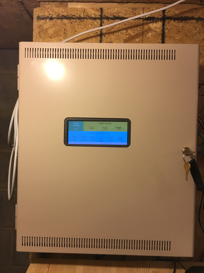
With basic power and sensors wired up, I mounted up the front panel of the box, which has the display for the Raspberry Pi mounted to it. (If you missed it, I shared some info when I did that several weeks ago - you can check out the details here.)
Next, I whipped up some code! To save time for those who may feel this post is already getting a little long, I'll share the details on that code another time, but if you're super interested, drop me a note and I will send you copies to do with as you please. The quick summary is that I have the Ardunio reading the voltage and current sensors, and it dumps that data out of it's serial port. I then have the raspberry Pi running a LAMP stack. A Python script running on the Pi reads the serial data and stores it in a mySQL database so I can explore and manipulate the data it captures using all the mySQL stuff I'm accustomed to. I also whipped up a little PHP web site (only accessible on my local network at the moment) that displays the data. I have the display on the front of the power box showing the page in full-screen mode all the time, and I can also pull it up on my browser any time I want as well - it's fun to pull it up and make contacts while watching the numbers change :-)
So there you have it - the shack power distribution update! There's still a lot of work to do on this, but at the moment I have functioning power for the rig and some task lights, and I'm recording data about my power usage. This means that when I get ready to drop some big back-up batteries on this situation, I'll have a good idea of what size of batteries to shoot for.
73 for now!




 RSS Feed


